Introduction
"Advanced technical ceramics" describes the engineered ceramic systems used in cutting tools, bearings, ballistic armor, semiconductor packages, thermal barrier coatings, and high-temperature structural components. They sit apart from traditional refractories by virtue of controlled composition, fine grain size, and very high relative density. The properties that make them useful in service (extreme hardness, chemical inertness, brittle fracture behavior) also make them among the most challenging materials to prepare metallographically.
This guide is the material-specific companion to our broader Ceramics Preparation guide. Where the general guide covers the principles of ceramic prep (sectioning theory, mounting choices, grinding and polishing fundamentals, etching technique), this one focuses on what differs between specific advanced technical ceramics: identity, applications, prep failure modes, and etching parameters.
How this guide is organized
Across these 10 advanced technical ceramics, the mechanical preparation is essentially the same. PACE's shared Class 10 procedure handles all of them through colloidal silica final polish. The exception is glass-ceramic, which needs a fine-grit sectioning blade rather than the medium-grit blade used for the others.
What varies meaningfully is material identity (formula, hardness, applications), prep failure modes (grain pullout, phase transformation, relief), and etching parameters. The page is organized around those differences: per-material reference first, then the shared procedure, then an etching parameters table consolidated across all 10.
Materials covered: alumina (Al2O3), zirconia (ZrO2), silicon carbide (SiSiC and dense monolithic SiC), silicon nitride (Si3N4), SIALON, ALON, mullite, cordierite, steatite, and alumino-silicate glass-ceramic.
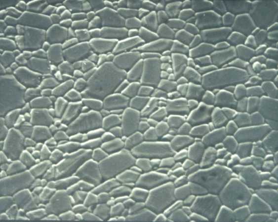
Alumina (Al2O3) microstructure after Class 10 prep and thermal etching. Grain boundary contrast comes from diffusion-driven groove formation during sub-sintering heat treatment.
Material Reference
Each material below shares the same Class 10 mechanical prep (see Shared Class 10 Procedure). What's documented here is identity, applications, and prep-specific risks. Etching parameters are consolidated in a single material-specific table in the Etching section.
Alumina (Al2O3) and Sapphire
Pure aluminum oxide. Hardness ~2000 HV, melting point 2072°C, chemically inert. Polycrystalline sintered alumina is used in wear plates, cutting inserts, electronic substrates, biomedical implants, and refractory linings. Single-crystal Al2O3 (sapphire) is used in optical windows, watch crystals, and high-end semiconductor wafers.
Prep risks: Grain pullout reads as porosity if the mount isn't tight. Edge rounding around the mount boundary unless a mineral-filled hot mount is used. In sapphire, sub-surface fracture from sectioning shows up as apparent porosity that wasn't there in the bulk crystal. Translucency of low-density alumina interferes with fluorescent-dye visualization of pores.
Zirconia (ZrO2)
Zirconium dioxide, typically partially stabilized with yttria (YSZ, 3-8 mol% Y2O3) or magnesia. Exhibits transformation toughening: under stress, the metastable tetragonal phase converts to monoclinic with a 4% volume expansion that arrests crack propagation. Used in thermal barrier coatings, biomedical implants (dental crowns, hip joints), oxygen sensors, and structural ceramics.
Prep risks: The same transformation toughening that makes zirconia useful in service is a prep failure mode. Mechanical stress from aggressive sectioning or grinding triggers local t→m transformation at the surface, leaving a damaged layer that prints as "apparent porosity" and that no amount of subsequent polishing removes. Counter-intuitively, higher wafering loads and speeds give cleaner cuts than light feeds, because the heat generated by light feeds drives more transformation than the brief mechanical contact of a firm cut. Thermal etching above ~1200°C also triggers t→m transformation. Stay below.
Silicon Carbide (SiC) and SiSiC
One of the hardest engineering ceramics, ~2500-3000 HV. Available in several forms: dense sintered SiC (SSiC) for ballistic armor and pump components; reaction-bonded SiC (SiSiC, silicon-bonded silicon carbide) which is more machinable due to a ductile Si phase; and CVD SiC for semiconductor processing components. Used in bulletproof plates, pump seals, kiln furniture, and brake rotors.
Prep risks: Extreme hardness means extended grinding and polishing times. Monolithic SSiC is among the materials where mechanical polishing alone often cannot remove sub-surface damage, and broad-beam ion polishing is the practical final step for SEM/EBSD work. SiSiC is easier because the Si phase polishes faster than the SiC grains, but the resulting phase relief can be misread as wear if not understood. Thermal etching in air will oxidize SiC above 1200°C; use inert atmosphere (Ar, N2) if going above that temperature.
Silicon Nitride (Si3N4)
Hard, tough, thermal-shock-resistant ceramic with hardness ~1500-1800 HV. Available as sintered (SSN), reaction-bonded (RBSN), or hot-pressed (HPSN). Most engineering Si3N4 contains a small glassy intergranular phase, formed from sintering aids like Y2O3 and Al2O3, that bonds the grains. Used in turbocharger rotors, ball bearings, engine valves, and cutting tools.
Prep risks: The glassy grain-boundary phase polishes faster than the Si3N4 grains, producing relief that the eye reads as grain definition but that is actually preferential removal of the bonding phase. With conventional 9 / 6 / 3 / 1 / 0.25 µm diamond progression, sub-surface damage persists even after long polishing. Colloidal silica chemical-mechanical polish (CMP) is essential to remove the damage layer and produce a flat, pullout-free surface. KOH molten salt etch and HF etch both work but preferentially attack the same glassy phase, so over-etching erases the grain boundary contrast you were trying to reveal.
SIALON
Silicon aluminum oxynitride, a solid solution of Si3N4 with Al and O substituting into the lattice (general formula Si6-xAlxOxN8-x). Combines high-temperature strength close to Si3N4 with better resistance to molten metal attack. Used in cutting tools for nickel-based superalloys, foundry pouring tubes, and wear-resistant components.
Prep risks: Cracking during sectioning is the dominant failure mode. The material is machinable but brittle, and excessive feed rate produces sub-surface cracks that propagate during grinding. Once present, these cracks cannot be polished out. The glassy grain boundary phase (similar to Si3N4) requires colloidal silica final polish. Etching with molten KOH preferentially attacks the grain boundary phase and reveals individual SIALON grains clearly.
ALON (Aluminum Oxynitride)
Cubic spinel-structured aluminum oxynitride, formula approximately Al23O27N5. Transparent, harder than sapphire (~1900 HV), and used in transparent armor windows, high-pressure optical windows, and missile domes. Marketed as Surmet's ALON®.
Prep risks: Two-phase microstructure (Al2O3-rich and AlN-rich domains) produces hardness-dependent relief during polishing. Some practitioners deliberately leave shallow relief to map the AlN-rich phase under DIC, while others CMP-flatten for quantitative work. Grain pullout in the softer AlN-rich domains is the failure mode if polish force is too high. Optical transparency makes the as-polished sample hard to image in brightfield; sputter coating with a few nanometers of Au or Pt before imaging is standard.
Mullite (Al6Si2O13)
Aluminum silicate refractory ceramic, melting point ~1880°C, hardness ~1100 HV. The principal phase in fired clay-based refractories, kiln furniture, and high-temperature insulation. Often present as the matrix phase in cordierite and steatite formulations as well.
Prep risks: Mullite is softer than alumina but still brittle. Porous mullite refractories pull out badly without vacuum impregnation. The needle-like (acicular) crystal habit in some mullite grades produces directional polishing artifacts; flatten with colloidal silica vibratory polish if quantitative work is needed. KHF2 molten salt etch attacks the glassy intergranular phase typical of fired refractory mullite.
Cordierite (Mg2Al4Si5O18)
Magnesium aluminosilicate with very low thermal expansion. Used almost universally for automotive catalytic converter substrates (the honeycomb monolith) and diesel particulate filters. Also kiln furniture and heat shock parts.
Prep risks: Almost always porous (honeycomb structures or extruded foam structures), so vacuum impregnation is mandatory and a fluorescent dye in the mounting resin is the standard way to distinguish design porosity from prep-induced pullout. Cordierite is relatively soft for an oxide ceramic; aggressive force during grinding causes edge rounding around the mount boundary. Brightfield imaging gives very low contrast on polished cordierite because of its small refractive-index difference with the mounting resin; switch to DIC or sputter coat for inspection.
Steatite (MgSiO3)
Magnesium silicate fired from talc-based formulations. Excellent electrical insulator, used in spark plug bodies, high-voltage standoffs, and kiln furniture. Hardness ~600-800 HV, lower than most ceramics in this guide.
Prep risks: Softer ceramics smear during fine grinding. Use lighter grinding forces (5-10 lbs) and watch for sub-surface deformation that the eye may read as polishing artifact. The talc-derived microstructure can include residual platelet structures that polish at different rates than the dominant enstatite (MgSiO3) phase. Edge rounding around the mount boundary is more pronounced than for harder ceramics; use mineral-filled compression resin if edge retention matters.
Alumino-Silicate Glass-Ceramic
Crystallized glass containing fine alumino-silicate crystals (lithium aluminosilicate or magnesium aluminosilicate, depending on formulation). Very low thermal expansion, impervious to water and most chemicals. Used in cookware (CorningWare, Pyroceram), missile radomes, telescope mirror blanks, and thermal protection systems.
Prep risks: This is the exception in the family. Damage during sectioning cannot be polished out. The crystalline phase is hard, but the residual glassy phase fractures conchoidally and propagates cracks far into the bulk. A fine-grit diamond wafering blade is mandatory; the medium-grit blade used for the other nine ceramics produces unacceptable edge chipping. Sub-surface damage from grinding shows up as polished pits that look like porosity. Polarized light shows the crystalline phase clearly against the glassy matrix without any etching.
Etching by Material
Many advanced ceramics show grain boundaries under DIC on a colloidal-silica-finished sample with no chemical or thermal etching at all. Try that first. Where additional contrast is needed, the table below lists the standard etching approaches by material.
Order of preference: optical revelation (DIC, dark-field, polarized), then vibratory polish with colloidal silica (chemical-mechanical action), then thermal etching, then molten salt or chemical etching. Use the least hazardous method that reveals what you need. See Ceramics Preparation, Etching section for full procedure detail on each method.
Material-Specific Etching Parameters
| Material | Preferred Approach | Etchant / Conditions | Time | Notes |
|---|---|---|---|---|
| Alumina (Al2O3) | Thermal etching | 1400-1500°C in air; or boiling H3PO4 (85 ml acid + 15 ml H2O) | 30-60 min thermal; 5 min to 2 hr chemical | High-purity alumina needs longer chemical times |
| Zirconia (ZrO2) | Thermal etching | 1100-1200°C in air; or boiling H2SO4 (50:50 with H2O) | 30-60 min thermal; 1-5 min chemical | Stay below ~1200°C to avoid t→m transformation |
| Silicon Carbide (SiC, SiSiC) | Thermal etching (inert atmosphere) | 1800-1900°C in Ar or N2; or molten NaHCO3/KHCO3 in Pt crucible | 30-60 min thermal; ~10 min molten salt | Air will oxidize SiC above 1200°C |
| Silicon Nitride (Si3N4) | Molten KOH or HF | Molten KOH in Pt/Ni crucible; or 48-50% HF immersion at RT | Seconds to minutes (KOH); 10-15 min (HF) | Both attack the glassy grain-boundary phase; HF is extreme hazard |
| SIALON | Molten KOH | Molten KOH in Pt crucible | Seconds to minutes | Reveals grains by attacking the glassy intergranular phase |
| ALON | DIC + sputter coat (often no etch) | Au or Pt sputter, 5-10 nm; thermal etch 1300-1400°C if more contrast needed | N/A (sputter); 30-60 min (thermal) | Optical transparency requires coating before brightfield imaging |
| Mullite | Molten KHF2 | Molten potassium hydrogen fluoride in Pt crucible | 5-10 min | Releases HF fumes; fume hood and HF PPE mandatory |
| Cordierite | DIC (often no etch) | Sputter coat for brightfield; thermal etch 1200-1300°C if needed | N/A; 30 min thermal | Honeycomb porosity is often the analysis target, not grain boundaries |
| Steatite | Thermal etching | 1100-1200°C in air | 30-60 min | Stay below sintering temperature (~1250-1300°C) |
| Glass-ceramic | Polarized light (no etch) | Crossed polarizers reveal crystalline phase against glassy matrix; HF immersion if chemical etching is needed | N/A (polarized); 30 sec to 2 min (HF) | HF preferentially attacks the glassy phase; extreme hazard |
Safety: Several etchants in this table involve extreme hazards. Hydrofluoric acid (HF) causes deep tissue burns that may not be immediately painful; HF-rated gloves and calcium gluconate gel are mandatory. Molten KOH and molten KHF2 are contact hazards and KHF2 releases HF fumes. Always work in a fume hood with appropriate PPE. Refer to the Safety Fundamentals guide before handling any of these etchants.
Troubleshooting
The general troubleshooting reference (chipping, scratches, grain pullout, no contrast, excessive prep time) is in Ceramics Preparation, Troubleshooting section. Below are problems specific to the advanced ceramics in this guide.
Apparent porosity in ZrO2 that wasn't in the bulk
Cause: Stress-induced t→m phase transformation from aggressive sectioning or grinding, locking in surface damage.
Fix: Use firmer wafering feed (not lighter), reduce grinding heat with continuous water, avoid thermal etching above 1200°C. If damage is already present, re-prep from the polishing step with reduced force.
Sub-surface damage in Si3N4 after long diamond polish
Cause: Conventional 9 / 6 / 3 / 1 / 0.25 µm diamond progression leaves sub-surface damage in Si3N4. The damage is not visible until etching, when it appears as a mottled surface or false grain structure.
Fix: Extend the SIAMAT colloidal silica final step to 5-10 min; the CMP action removes the damage layer. Vibratory polish with colloidal silica for 1-4 hours is even better for quantitative work.
Edge chipping in glass-ceramic after sectioning
Cause: Medium-grit wafering blade used instead of fine-grit. Damage at the cut edge propagates into the body and cannot be removed by polishing.
Fix: Re-section with a fine-grit diamond wafering blade. There is no recovery path once chipping is present.
Featureless brightfield image on ALON or cordierite
Cause: Optical transparency or low refractive-index difference with the mounting resin reduces brightfield contrast to near zero.
Fix: Sputter coat with 5-10 nm Au or Pt before imaging, or switch to DIC or dark-field, which exploit surface relief rather than transmission/reflection.
Cracks in SIALON after sectioning
Cause: Feed rate too high during precision sectioning. Cracks propagate into the bulk during grinding.
Fix: Use slow controlled feed (2-5 mm/min) and copious coolant. Inspect immediately after cutting; any visible cracks mean re-section. Once in grinding, cracks become permanent.
Phase relief that isn't pullout in SiSiC or ALON
Cause: Two-phase microstructure with hardness mismatch. The softer phase (Si in SiSiC, AlN-rich domains in ALON) polishes faster than the harder phase, producing relief that can be misread as pullout.
Fix: Confirm with DIC at high magnification. Pullout shows sharp-edged voids; relief shows continuous height differences. If relief is unwanted, extend colloidal silica final polish to flatten. If pullout is the actual problem, reduce force at the failing polishing step.
Additional Reading
- Zipperian, D.C. Metallographic Handbook. PACE Technologies, Tucson, AZ. house reference for prep procedures.
- ASM Handbook, Vol. 9: Metallography and Microstructures. ASM International. sections on ceramics preparation, thermal etching, and chemical etchants.
- Weidmann, E. and Guesnier, A. "Metallographic preparation of thermal spray coatings." Struers Application Notes. relevant for ceramic coatings, vacuum impregnation, and the fluorescent-dye porosity-visualization technique.
- Weidmann, E., Guesnier, A., and Bundgaard, H. "Metallographic preparation of microelectronics." Struers Application Notes. relevant for multilayer ceramic capacitors and ceramic-on-metal interfaces.
- Petzow, G. Metallographic Etching, 2nd ed. ASM International. comprehensive ceramic etchant reference, including thermal and molten-salt etching procedures.
- ASTM E1920. Standard Guide for Metallographic Preparation of Thermal Sprayed Coatings (procedural parallels apply to bulk ceramics).
- ASTM C1326 / C1327. Standard Test Methods for Knoop and Vickers Indentation Hardness of Advanced Ceramics.
- ASTM E1245. Automatic Image Analysis (for porosity and grain size measurement on ceramics).
- Chinn, R.E. Ceramography: Preparation and Analysis of Ceramic Microstructures. ASM International / Wiley. the definitive ceramic-specific metallography reference.
Explore More Procedures
For the general ceramic preparation principles (sectioning theory, mounting choices, full troubleshooting), see the broader guide. For composite ceramics with fiber or particulate reinforcement, see the Ceramic Matrix Composite guide.