Introduction
Sectioning is the first step in metallographic sample preparation. The goal is straightforward: cut a representative sample from the bulk workpiece with as little damage as possible, so the grinding and polishing that follow can remove any cut-induced damage and reveal the true microstructure.

PACE MAXCUT abrasive cut-off blades and PICO-series precision wafer blades cover the full range of metallographic sectioning needs.
Every sectioning operation can be judged by the same set of effects.
Desirable effects
- Flat cut, located close to the area of interest
- Minimal microstructural damage
Undesirable effects
- Smeared (plastically deformed) metal
- Heat-affected zones or burning
- Excessive subsurface damage, including cracking in ceramics
- Damage to secondary phases, such as graphite flake or nodule loss in cast iron and grain pull-out
The goal of any cut is to maximize the desirable effects while minimizing the undesirable ones.
Two methods cover almost all metallographic sectioning: abrasive sectioning for routine metal samples, and precision wafer cutting for delicate, brittle, electronic, or thin-section work. The two methods use different blades, different machines, and different parameter ranges. The choice between them shapes everything downstream.
Sample Planning
Before any blade touches the part, two decisions matter: where to cut and how to orient the cut. Both determine whether your final polished surface answers the question you are trying to answer.
Locate the area of interest
The cut should pass close to the feature you want to examine: a weld fusion zone, a fracture surface, a case-hardened layer, a coating interface, a specific grain orientation. For directional features like welds, columnar castings, or fiber-reinforced composites, the cut plane and the feature orientation determine what you will and will not see at the microscope.
Allow for the damage zone
Sectioning always introduces some surface and subsurface damage. Cut at least 1 to 2 mm away from your true area of interest so that grinding can remove the damaged layer and you reach a clean microstructure. For soft, ductile metals (aluminum, copper, lead), allow 2 to 3 mm; deformation runs deeper in soft materials. See the Grinding Techniques guide for how the damage layer is removed in the next step.
Keep coatings in compression
When sectioning a coated or plated sample, orient the cut so the blade enters the coating and exits through the base material. This keeps the coating in compression during the cut and prevents it from spalling or chipping off at the substrate interface. The same orientation rule applies whether you are using an abrasive blade or a precision wafer blade.
Quick checks before cutting
- Is the cut as close to the area of interest as your damage allowance permits?
- Will the cut pass through the smallest practical cross-section?
- For coatings or layered structures, is the orientation correct for compression?
- For directional features (welds, fibers, columnar grains), does the cut plane reveal what you need to see?
Choosing Your Method
Abrasive sectioning and precision wafer cutting are not interchangeable. Pick the one that matches your sample size, material, and damage tolerance.
| Abrasive Sectioning | Precision Wafer Cutting | |
|---|---|---|
| Typical use | Routine metal samples, high throughput | Delicate, brittle, thin, or precision-located cuts |
| Sample size | Up to ~150 mm depending on blade diameter (10–16 inch) | Small samples, typically ≤ 50 mm |
| Damage | Higher; some heat-affected zone | Very low; near machining quality |
| Cut speed | Fast (seconds to minutes) | Slow (minutes to hours) |
| Kerf width | 1.5–2.5 mm standard, ~1.0–1.5 mm with reinforced thin blades | 0.1–0.5 mm |
| Cost per cut | Low; abrasive blades are inexpensive | Higher; diamond/CBN blades and longer cut times |
| Choose when | Routine metals, plastics, polymer or metal matrix composites, high throughput, larger samples | Brittle ceramics, electronic substrates, thin films, bone, composites with delicate fibers, or any cut where damage and material loss must be minimized |
The rest of this guide is split into two self-contained tracks. Read Abrasive Sectioning if you are cutting routine metal samples. Read Precision Wafer Cutting if you are cutting brittle, delicate, or precision-located samples. Universal Best Practices and Troubleshooting apply to both.
Abrasive Sectioning
Abrasive sectioning uses a rotating, bonded abrasive wheel to cut through metals, plastics, and many composites. It is the workhorse of metallographic sample prep: fast, versatile, inexpensive per cut, and capable of handling a wide range of materials from soft aluminum to case-hardened tool steel.
How abrasive cutting works
An abrasive blade is built from abrasive particles held together by a bonding matrix. As the wheel rotates, particles at the cutting edge fracture or wear, exposing fresh abrasive while removing material from the workpiece. The right combination of abrasive type and bond hardness matches the breakdown rate of the bond to the wear rate of the abrasive, so the blade keeps presenting sharp particles to the cut.
Abrasive types
- Alumina (aluminum oxide): moderately hard and relatively tough. The default choice for ferrous metals.
- Silicon carbide: very hard, but fractures and cleaves easily, which makes it self-sharpening. Better suited to non-ferrous metals like aluminum, titanium, and zirconium alloys.
Bond types: resin vs. resin-rubber
The bond matrix has a bigger effect on cutting behavior than most operators realize, and the trade-offs come down to smell, life, and forgiveness.
- Resin-bonded: less odor, breaks down faster (continuously renewing the cutting abrasive), produces a modestly cleaner cut, and is less likely to burn the sample. More versatile across materials.
- Resin-rubber bonded: longer service life, more aggressive cutting, but produces the familiar burnt-rubber smell and is more likely to burn the sample if parameters are wrong. Finding the right resin-rubber hardness, abrasive size, and thickness for a given material historically required experimentation, which is why resin-only formulations have steadily taken over.
PACE MAXCUT blade selection
PACE Technologies manufactures the MAXCUT line of abrasive cut-off wheels. Each series is formulated for a specific material class. Use the table below to select the correct series, then pick the size that matches your cutter's wheel capacity.

PACE MAXCUT abrasive blades. Each series is formulated for a different material class.
| Material | Composition | 10″ | 12″ | 14″ | 16″ |
|---|---|---|---|---|---|
| Soft non-ferrous (aluminum, brass, zinc) | Alumina, resin bonded | MAX-E250 | MAX-E300 | MAX-E350 | MAX-E400 |
| Hard non-ferrous (titanium, zirconium) | Silicon carbide, resin-rubber bonded | MAX-C250 | MAX-C300 | MAX-C350 | MAX-C400 |
| Soft steels | Alumina, resin bonded | MAX-E250 | MAX-E300 | MAX-E350 | MAX-E400 |
| Hard and case-hardened steels | Alumina, resin bonded | MAX-VHS250 | MAX-VHS300 | MAX-VHS350 | MAX-VHS400 |
| General steels and ferrous metals | Alumina, resin bonded, reinforced thin | MAX-D250T | MAX-D300 | MAX-D350 | MAX-D400 |
| Universal thin blade | Alumina, resin-rubber bonded | MAX-A250 | MAX-A300 | MAX-A350 | MAX-A400 |
| Industrial general-purpose thin blade | Alumina, resin bonded | MAX-I250 | MAX-I300 | MAX-I350 | MAX-I400 |
Picking blade diameter: use the smallest wheel that can still accommodate your sample. Larger wheels cut larger pieces but generate more heat and waste more material as kerf. The size suffix in the SKU (250, 300, 350, 400) is the wheel diameter in millimeters.
For the full SKU list, pricing, and stock, visit the Abrasive Cutting Consumables page.
Abrasive cutting parameters
Most metallographic abrasive cutters run at a fixed wheel speed. Typical speeds are 2,800 to 3,800 RPM for 10–14″ wheels. Your primary adjustable variables are feed rate, force, and coolant flow.
Feed rate and force
Apply steady, moderate force. Light pulsing motion often produces the cleanest cut and the longest blade life. Forcing the cut generates excess heat, causes premature blade wear, and risks burning the sample. Too little force lets the blade glaze over and stop cutting effectively. Let the blade do the work.
Coolant
Continuous coolant flow is mandatory in abrasive cutting. It serves four jobs: it removes heat from the cut zone, flushes swarf and degraded abrasive away from the kerf, lubricates the cutting action, and prevents material from welding to the blade. For abrasive cutting specifically, the coolant should have a relatively high flash point, since abrasive cutting routinely produces sparks at the cut zone.
PACE supplies water-based abrasive cutting fluids formulated for metallographic work. For older cast-iron-base cutters, the right fluid also serves as a corrosion inhibitor.
Hood-open tip: a closed saw hood traps coolant humidity and creates a corrosive chamber when the saw is idle. Keep the hood open between sessions to extend the life of the table, fixtures, and exposed metal parts.
Recommended PACE abrasive saws
PACE makes a complete line of MEGA abrasive cutters covering hands-on manual operation, manual table feeds, and fully automated production cutting.

MEGA-M250S, Economical Manual
250 mm wheel with manual wheel feed. The entry-point cutter for labs that need hands-on control on a budget.

MEGA-T250S / T300S / T350S / T400S, Manual Workhorses
Manual wheel and manual table feed in 250, 300, 350, and 400 mm wheel sizes. Step up the wheel size as your sample size grows.

MEGA-T300A / T350A / T400A, Automated
Programmed feed for repeatability, throughput, and operator safety. Best for high-volume labs and reproducible cut quality.
Precision Wafer Cutting
Precision wafer cutting uses a thin diamond or cubic boron nitride (CBN) blade on a slow, micrometer-adjustable saw. The thin kerf, slow cutting action, and fine abrasive size produce cuts with minimal damage and very low material loss. It is the right method for delicate samples, precision-located cuts, and any material where sectioning damage would compromise the final microstructure.
Dr. Donald Zipperian demonstrates precision sectioning on PACE Technologies equipment.
When to use precision wafer cutting
- Brittle materials: ceramics, glass, semiconductors, minerals
- Thin samples or thin sections (under 1 mm)
- Composites with delicate fibers (boron, ceramic fiber, carbon-carbon)
- Bone, hard tissue, and biological samples
- Heat-sensitive materials
- Cuts that need to land at a specific feature (failure analysis, electronic components)
- Any application where damage and material loss must be minimized
Blade types
- Diamond, metal-bonded (rim-pressed): the most common precision wafering blade. Diamond particles pressed into a metal binder along the rim of the blade. Long life, broad applicability.
- CBN (cubic boron nitride): use instead of diamond for materials that dull diamond, especially high-carbon and heat-treated steels. Diamond reacts with iron at cutting-zone temperatures and degrades quickly; CBN does not.
- Electroplated diamond: single layer of diamond grit on a metal core, producing a much higher, rougher abrasive profile. Used for soft and "gummy" materials (bone, plastics, rubbery composites) where a smooth blade would clog.
- Thin resin-rubber abrasive on wafer saw: less common, but possible for some materials. Requires at least 3,500 RPM and frequent coolant changes (heavy debris generation).
Diamond and CBN blade selection
Three parameters define a wafer blade: abrasive size, abrasive concentration, and bond/blade type. Of these, abrasive size dominates damage performance, and concentration determines how much load the blade tolerates.
| Grit | Particle size | Equivalent |
|---|---|---|
| Fine | 10–20 μm | ~600 grit |
| Medium | 60–70 μm | ~220 grit |
| Coarse | 120 μm | ~120 grit (mostly electroplated blades) |
Concentration is expressed as a percentage. High Concentration (HC) ≈ 100%, Low Concentration (LC) ≈ 50%. PACE diamond wafer blades carry the WB- prefix with LC or HC suffix (for example, WB-0055LC = 5-inch diameter, low concentration). PACE CBN wafer blades use the WCBN- prefix. PACE electroplated diamond blades use WB-…EPD.
Two principles for picking grit and concentration
- Finer abrasive = less damage. For extremely brittle materials (silicon, GaAs, glasses, ceramic composites, boron-graphite), a fine grit blade is often the only way to leave a microstructure that can be polished to truth. Coarser grits introduce damage that subsequent grinding may not fully remove.
- Concentration scales with material toughness. Brittle materials (ceramics) cut better with low concentration: fewer cutting points, each carrying more load, which suits brittle fracture-driven cutting. Ductile materials (metals, plastics) cut better with high concentration: more cutting points spreading the load.
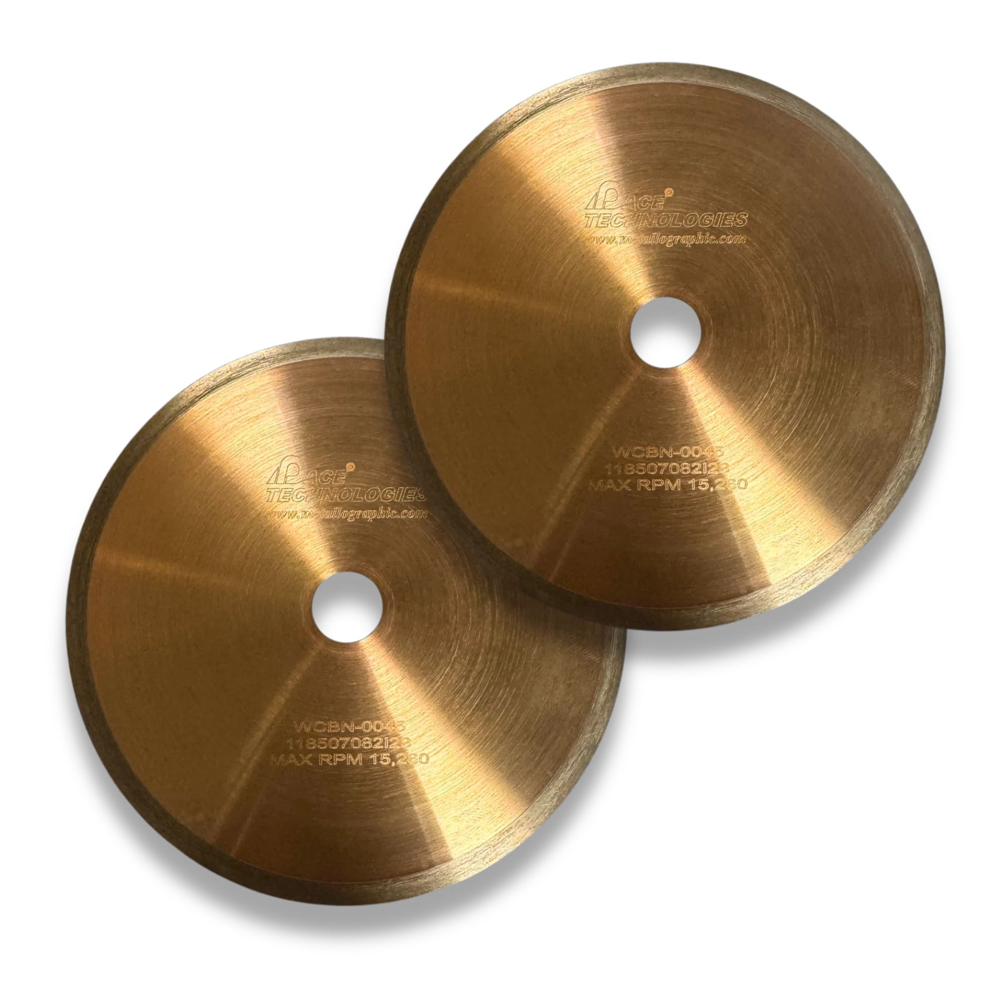
PACE WB-series diamond and WCBN-series CBN wafer blades.

PACE WB-…EPD electroplated diamond blades for soft and gummy materials.
Wafer cutting parameters by material
The table below collects PACE's recommended starting points for speed, load, and blade selection across material categories.
| Material | Characteristic | Speed (RPM) | Load (g) | Blade (grit / conc.) |
|---|---|---|---|---|
| Silicon substrate | Soft / brittle | <300 | <100 | Fine / Low |
| Gallium arsenide | Soft / brittle | <200 | <100 | Fine / Low |
| Boron composites | Very brittle | 500 | 250 | Fine / Low |
| Ceramic fiber composites | Very brittle | 1000 | 500 | Fine / Low |
| Glasses | Brittle | 1000 | 500 | Fine / Low |
| Minerals | Friable / brittle | >1500 | >500 | Medium / Low |
| Alumina ceramic | Hard / tough | >1500 | >500 | Medium / Low |
| Zirconia (PSZ) | Hard / tough | >3500 | >800 | Medium / Low |
| Silicon nitride | Hard / tough | >3500 | >800 | Medium / Low |
| Metal matrix composites | Varies | >3500 | >500 | Medium / High |
| General purpose | Varies | Variable | Variable | Medium / High |
Counter-intuitive but true: hard, tough ceramics cut better at HIGH speed and HIGH load. For materials like partially-stabilized zirconia (PSZ), silicon nitride, and dense alumina, low-speed and low-load cuts produce lateral cracking and grain pull-out, while high-speed and high-load cuts produce a clean kerf. The reason: at high speed and load, the crack propagates in the direction of the cut rather than laterally into the specimen. For softer brittle materials (silicon, GaAs, glasses), the opposite holds. Match the parameters to the material's response, not to your intuition.
For the full PACE wafer blade catalog with stock and pricing, see the Precision Wafering Consumables page.
Wafer cutting procedure
- Dress the blade with a ceramic dressing stick before cutting. (See Blade Dressing below for why this matters.)
- Clamp the specimen firmly. If possible, clamp both sides of the specimen; this eliminates the cutting burr that otherwise forms at the end of the cut.
- For brittle materials, clamp with a rubber pad between the jaws and the specimen. The pad absorbs cutting-zone vibration and protects the sample from fracturing.
- Start the cut with reduced force to establish the kerf, then bring the load up to the target value once the blade is tracking cleanly.
- Orient through the smallest practical cross-section. A shorter cut path means less time, less heat, and less risk of damage.
- For coated samples, cut through the coating and exit into the substrate (coating in compression, the same rule as abrasive sectioning).
- Use the largest blade flanges that fit your saw. Larger flanges support the thin blade and prevent wobble or flexing.
- Reduce force at the end of the cut for brittle samples. The blade exiting the material is when end-fracture is most likely.
- Use the appropriate cutting fluid (see below).
Blade dressing, what it actually does
Most operators dress wafer blades occasionally and assume they are "renewing the diamond." That is not what is happening. The diamond is still there. What is failing is the bond.
During cutting, the metal bond around each diamond particle smears slightly with each rotation. Over many cuts, the smeared bond blinds the cutting edge of the diamond, covering it and preventing it from biting into the workpiece. The cut rate drops with each successive cut. Dressing with a ceramic-abrasive-in-soft-matrix stick removes the smeared bond and exposes fresh diamond. After dressing, the blade cuts like new again.
Three rules for dressing:
- Always use a dressing fixture. Free-hand dressing chips and breaks blades.
- Light load: less than 200 grams. The goal is to abrade away smeared bond, not to grind the blade.
- Low speed: less than 300 RPM. Same reasoning.
Dress before each cutting session, and again any time cut rate begins to fall.
Wafer cutting fluid
Use a continuous coolant supply directed at the cut zone. Two families of cutting fluid are common:
- Water-based: easier to clean off samples and machine parts. Most common for routine wafer cutting.
- Oil-based: better lubrication, longer blade life on demanding cuts, but harder cleanup.
A good cutting fluid removes and suspends swarf, lubricates the blade-sample interface, and inhibits corrosion of the sample, blade, and machine. For reactive metals (magnesium, lithium, sodium alloys), use a non-aqueous fluid.
Recommended PACE precision wafering saws

PICO-155S and PICO-155P
Gravity-feed precision wafering saws. The 155S uses digital controls; the 155P uses analog. Both handle small samples with variable speed and load control.

PICO-200S, Manual Table Feed
Manual table-feed precision saw with capacity for larger or irregularly-shaped specimens. Best for high-accuracy research and industrial cuts that do not require automation.

PICO-200A, Automated Table Feed
Fully automated precision wafer cutting. Programmed feed for repeatable cut quality, ideal for production failure analysis and serialized samples.
Universal Best Practices
These habits apply to every cut, abrasive or precision.
Before the cut
- Mark the cutting plane on the sample clearly
- Clean the sample to remove surface contamination that could affect blade performance
- Verify the blade is properly mounted, balanced, and free of visible damage
- Check coolant level and condition; replace dirty fluid
- Wear appropriate PPE: safety glasses, hearing protection on abrasive cutters, gloves when handling sharp samples
During the cut
- Apply steady, consistent force; let the blade do the work
- Maintain continuous coolant flow over the cut zone
- Watch for excessive heat, smoke, discoloration, or unusual sounds; all are signs of a problem
- Do not force the cut. If it slows down, reduce force or check the blade rather than pushing harder
- For deep cuts, retract slightly to allow flushing and cooling, then re-engage
After the cut
- Let the sample cool before handling, especially after abrasive cutting
- Clean cutting fluid and swarf from the sample
- Inspect the cut surface for cracks, smearing, or burning
- Document the parameters that worked (and the ones that did not) for future reference
- Inspect the blade for wear or damage before storing
Blade and equipment care
- Store blades flat in a dry location; humid storage corrodes metal-bonded wafer blades
- Keep the saw hood open when the cutter is not in use to prevent corrosive humidity buildup
- Dress wafer blades before each session and any time cut rate drops (see Blade Dressing)
- Replace abrasive blades when cutting becomes inefficient or quality degrades; cracked or chipped blades are unsafe
- Keep a usage log so blade replacement schedules can be optimized
Test cuts pay for themselves. For critical or one-of-a-kind samples, make a test cut on a similar material first. It costs minutes and verifies that your parameters will not damage the real specimen.
Troubleshooting
Most sectioning problems resolve with the same handful of adjustments: change the blade, change the force, change the coolant. Use the table below to narrow down the cause before reaching for a different blade.
| Problem | Common causes | Solutions |
|---|---|---|
| Excessive heat or burning (smoke, discoloration, blue tint) |
|
|
| Excessive deformation or smearing (distorted microstructure, work-hardened surface) |
|
|
| Chipped or broken blade |
|
|
| Poor cut quality (rough, uneven, wandering) |
|
|
| Cutting too slow (low material removal) |
|
|
| End-of-cut burr (wafer) |
|
|
| Excessive blade wear |
|
|
Frequently Asked Questions
How close to the area of interest can I cut?
At least 1 to 2 mm away for most materials, 2 to 3 mm for soft ductile metals like aluminum, copper, and lead. The sectioning damage zone has to be removed by grinding, and the damage runs deeper in soft materials. Cutting closer than the damage zone means the next step grinds past your area of interest before clearing the damaged layer. Cutting farther wastes grinding time and risks introducing additional damage during planarization. If you need to cut closer than 1 mm, use a precision wafer saw instead of an abrasive cutter.
Do I really need a different blade for every material, or can I just use one?
You can get away with one blade for routine work in a single material class, and the MAX-A and MAX-I universal thin blades exist precisely for labs that cannot justify a full set. But matching the blade to the material dramatically improves cut quality, blade life, and the chance of finishing the cut without burning the specimen. Hard materials cut with a soft-bond blade burn quickly; soft materials cut with a hard-bond blade glaze and produce poor cuts. The MAXCUT selection table maps materials to the correct series. Read it once, save hours later.
When should I use CBN instead of diamond?
Use CBN for high-carbon and heat-treated steels. Diamond reacts chemically with iron at cutting-zone temperatures, which dulls the diamond rapidly on hardened ferrous materials. CBN does not react with iron and holds its edge much longer on those alloys. For ceramics, glasses, electronic materials, and non-ferrous alloys, diamond is still the better choice.
What kerf width should I expect?
Standard abrasive cut-off blades have a kerf of 1.5 to 2.5 mm. Reinforced thin abrasive blades (MAX-D-RT, MAX-A, MAX-I) cut a narrower kerf in the 1.0 to 1.5 mm range. Precision wafer blades are far thinner: 0.1 to 0.5 mm. If material loss matters (rare samples, very thin sections, or cuts where you need both halves intact), the wafer blade's kerf advantage can be decisive.
How often should I dress my wafer blade?
Dress before each cutting session, and again any time the cut rate noticeably drops. Dressing is fast (under a minute with the right fixture) and restores a blinded blade to like-new cutting performance. Use a ceramic dressing stick, less than 200 g of load, and less than 300 RPM, always in a dressing fixture.
Why did my sample turn blue or discolored when I cut it?
Bluish or burnt discoloration on a freshly cut surface is thermal damage. The blade generated heat faster than the coolant could remove it. The most common causes are cutting force too high, blade speed too fast for the material, insufficient coolant flow, or a glazed/dull blade trying to cut through hard material. Reduce force, increase coolant flow, and verify the blade is appropriate for the material (MAX-VHS for hard and case-hardened steels). The blue layer must be removed during grinding before the true microstructure is visible, so factor extra grinding allowance into the next step.
My cut came out wedged or not square. What went wrong?
A wedged cut almost always means the specimen moved during cutting or the clamping fixture slipped. Re-secure the specimen, clamping both sides if your fixture allows; this also eliminates the burr that otherwise forms at the end of a wafer cut. On precision saws, use the largest blade flanges your machine accepts to prevent thin blades from flexing during the cut. For abrasive cutting, verify the table is square and the specimen is fully seated before starting. A consistently wedged cut from the same saw with otherwise sound technique suggests fixture wear and an equipment service call.
My ceramic samples crack during cutting. What am I doing wrong?
For hard, tough ceramics (PSZ zirconia, silicon nitride, dense alumina), this is the counter-intuitive case: try cutting at higher speed and higher load, not lower. At high speed and load the crack propagates in the direction of the cut rather than laterally into the specimen. For softer brittle materials (silicon, GaAs, glasses), the opposite holds: drop speed and load, and use a finer blade. Always clamp brittle samples with a rubber pad to absorb vibration, and reduce force at the end of the cut.
Manual or automated cutter, which should I buy?
Choose manual (MEGA-T series, PICO-155, PICO-200S) if your lab does varied cutting on a moderate volume and an operator is present for every cut. Automated cutters (MEGA-T*A series, PICO-200A) pay back through reproducibility, throughput, and operator safety. They are the right choice for production failure analysis, serialized parts, or any lab where the same cut is repeated dozens of times per day. Automated saws also remove operator-to-operator variability from cut quality.
What's Next: Mounting
Once your sample is cut, the next step is to mount it. Mounting holds the specimen at a known orientation, protects the edges during grinding, and gives the operator something to handle safely. Without mounting, the cut sample can deform under grinding pressure, edges round over, and small samples are unsafe to hold against an abrasive.