
Class 4 encompasses semiconductors, functional ceramics, and multilayer electronic components that share a defining combination: moderate hardness with extremely low fracture toughness. Silicon, gallium arsenide, piezoelectric ceramics (PZT), ferrites, aluminum nitride substrates, and multilayer devices (MLCCs, MEMS) are all brittle enough to fracture, cleave, or delaminate under the forces used in standard metallographic preparation. Many contain layered structures with micron-scale features that require very flat, relief-free surfaces to analyze. Preparation must balance material removal against fracture and delamination risk at every step.
Preparation Characteristics & Challenges
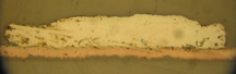
MEMS Device (Si-Ni-Au), as-polished. Example of Class 4 multilayer electronic material
Class 4 materials exhibit several distinctive properties that directly impact how they must be prepared:
Extreme Brittleness
All Class 4 materials fracture rather than deform under mechanical stress. Silicon cleaves along crystallographic planes, GaAs shatters unpredictably, and ceramics (PZT, ferrites, AlN) develop subsurface cracks that propagate during subsequent preparation steps. Coarse grinding is the most damaging step: subsurface crack networks from aggressive material removal can extend 50-100 µm below the surface and require extensive polishing to remove. Use the finest practical starting grit and very light force throughout.
Layer Delamination
MLCCs contain hundreds of alternating ceramic and electrode layers, each a few microns thick. MEMS devices combine silicon, metals, and thin-film materials in complex three-dimensional structures. Excessive grinding or polishing force separates these layers, and once delamination starts it propagates rapidly. Vacuum impregnation with low-viscosity epoxy before grinding stabilizes layer interfaces. Use light, consistent pressure and avoid sudden force changes during preparation.
Relief Between Dissimilar Materials
Layered structures contain materials with very different hardness and polishing rates. Metal electrodes in MLCCs are softer than the surrounding barium titanate ceramic, creating depressions at every layer. Silicon polishes faster than nickel or gold in MEMS devices. Relief obscures the fine features that are usually the reason for preparing these specimens. Use napless cloths exclusively, keep polishing times short, and apply uniform pressure across the specimen to minimize differential removal.
Subsurface Damage Propagation
Unlike metals, where grinding damage is limited to a thin deformed layer, brittle materials develop crack networks that extend far below the grinding surface. Each subsequent preparation step must remove the full depth of damage from the previous step, or residual cracks will be visible in the final specimen. Progress through grit sizes without skipping steps, and verify at each stage that previous damage has been fully removed before continuing.
Micron-Scale Feature Preservation
The features of interest in Class 4 materials are often at the micron or sub-micron scale: thin-film metallization layers, wire bonds, solder joints in MLCCs, electrode patterns in MEMS, domain boundaries in PZT. These features require an extremely flat, scratch-free surface to be visible under the microscope. Even minor surface relief or residual scratching can obscure the analysis target. Final polish quality is paramount.
Target Plane Preparation
Many Class 4 specimens require grinding to a specific internal plane (a particular layer, a wire bond cross-section, or a defect location). This target grinding demands precise control of material removal rate and frequent optical verification of progress. Overshoot by even a few microns and the feature of interest is lost. Use controlled-removal grinding equipment or lapping films with frequent inspection under a stereo microscope as the target plane is approached.
Chemical Sensitivity
GaAs is attacked by many common polishing and cleaning chemicals. PZT can be affected by acidic solutions. Some thin-film metallizations dissolve in standard etchants. Verify chemical compatibility before using any new preparation product on Class 4 specimens. Water-based diamond suspensions and pH-neutral colloidal silica are generally safe. Avoid alkaline or acidic cleaning solutions unless confirmed compatible with all materials in the specimen.
Class 4 Materials
The following materials are classified as Class 4 (Soft, Brittle Non-metals). Click on any material to view its detailed preparation procedures.
Semiconductors
Functional Ceramics
Multilayer Electronic Components
Preparation Guide
Recommended Preparation Steps
Sectioning
Use a low-speed precision diamond wafering saw with a thin resin-bonded or electroplated diamond blade and continuous coolant. Feed force must be minimal (gravity feed or very light spring loading) to prevent fracture and edge chipping. For silicon and GaAs wafers, orient the cut to avoid cleavage planes where possible. MLCCs and MEMS devices are often too small for clamping and should be potted in epoxy first, then sectioned through the mount. For target cross-sections, approach the plane of interest slowly with frequent optical checks under a stereo microscope.
Mounting
Castable (cold) epoxy with vacuum impregnation is essential for all Class 4 materials. Vacuum impregnation fills internal voids in porous ceramics, stabilizes the interfaces between layers in MLCCs and MEMS, and provides mechanical support to prevent fracture during grinding. Use low-viscosity, low-shrinkage epoxy to minimize stress on the specimen during cure. Compression mounting must never be used; the heat and pressure will fracture, delaminate, or permanently alter these materials. For cross-sectional analysis of small components, pot multiple specimens in a single mount for efficiency.
Grinding
Start at 600 grit SiC or finer to minimize subsurface fracture depth. For multilayer components and target plane preparations, diamond lapping films (30 µm, then 15 µm, then 9 µm) provide better control of material removal than SiC papers. Progress through 800, 1200, and 2400 grit with very light pressure (5-10 N per 30 mm mount). Use contra-rotation at low speed (100-150 RPM). Check progress frequently under the microscope, especially when grinding toward a target plane. Thoroughly clean between every grit change to prevent coarse particles from causing fracture on finer steps.
Polishing
Use napless cloths exclusively to maintain flatness and minimize relief between dissimilar materials. Polish with 3 µm diamond suspension, then 1 µm diamond, followed by 0.05 µm colloidal silica on a napless or chemically resistant pad. Use very light pressure (5-10 N) and short polishing times (30-60 seconds per step) to prevent differential material removal. Contra-rotation reduces directional artifacts. For specimens where maximum flatness is critical (MLCC electrode analysis, MEMS layer measurements), vibratory polishing with colloidal silica for 1-4 hours produces the best results with minimal relief.
Etching
Most Class 4 materials are examined as-polished or with optical contrast techniques (DIC, polarized light, darkfield) rather than chemical etching. Layer structures, voids, cracks, and electrode patterns are typically visible without etching. When etching is needed, use material-specific solutions with caution: dilute HF for silicon grain boundaries, molten KOH or bromine-methanol for GaAs defect decoration. PZT and ferrites are rarely etched chemically; thermal etching (brief heating in air) can reveal grain boundaries without chemical attack. Always verify etchant compatibility with all materials present in multilayer specimens before proceeding.
Quality Verification
No delamination between layers in multilayer components (MLCCs, MEMS)
Minimal relief between dissimilar materials at layer interfaces
No subsurface fractures or cleavage cracks visible under 200x magnification
Micron-scale features (electrodes, thin films, wire bonds) clearly resolved
Target cross-section plane reached without overshooting the feature of interest